Heya! I thought I’d mention that I’ve been doing a bunch of development on the optical Timex Datalink watches! I have been carefully sniffing data from the original Timex software with a logic analyzer, and have fully reverse engineered every Datalink protocol, the serial Notebook Adapter, and even the CRT syncing graphics! This means that every Datalink device, including every Timex and Motorola watch, all PDAs, and the funny e-BRAIN talking toy is supported!
For those that aren’t familiar, the Timex Datalink is a watch that was introduced in 1994 that is essentially a small PDA on your wrist. The early models (supported by this software) have an optical sensor on the top of the face that receives data via visible light.
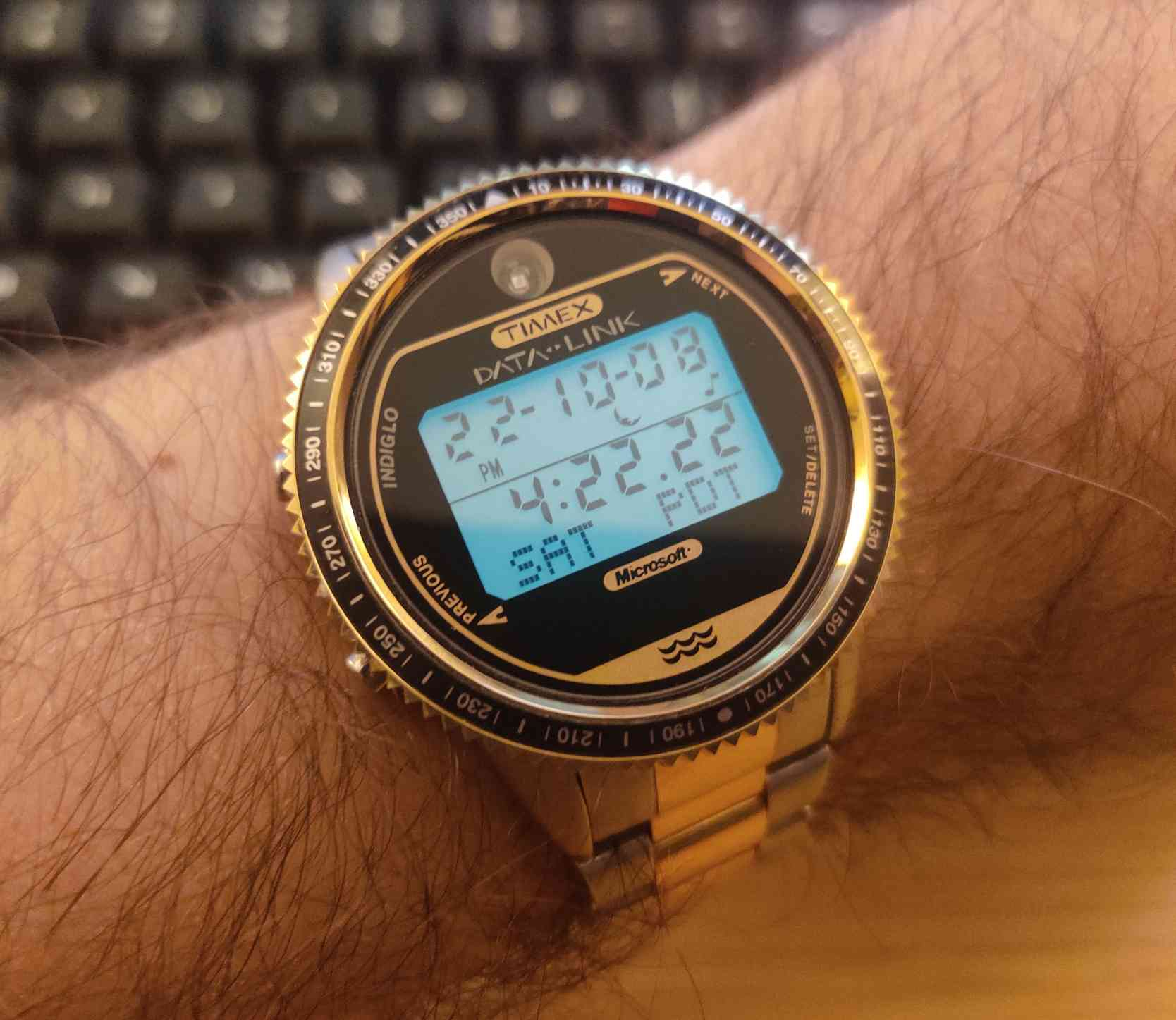
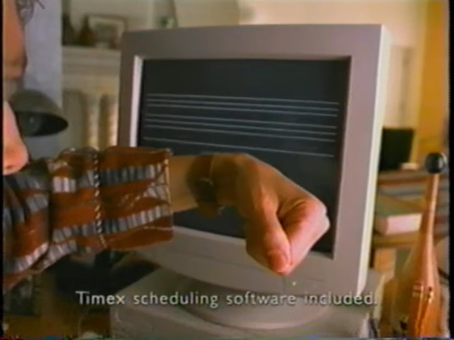
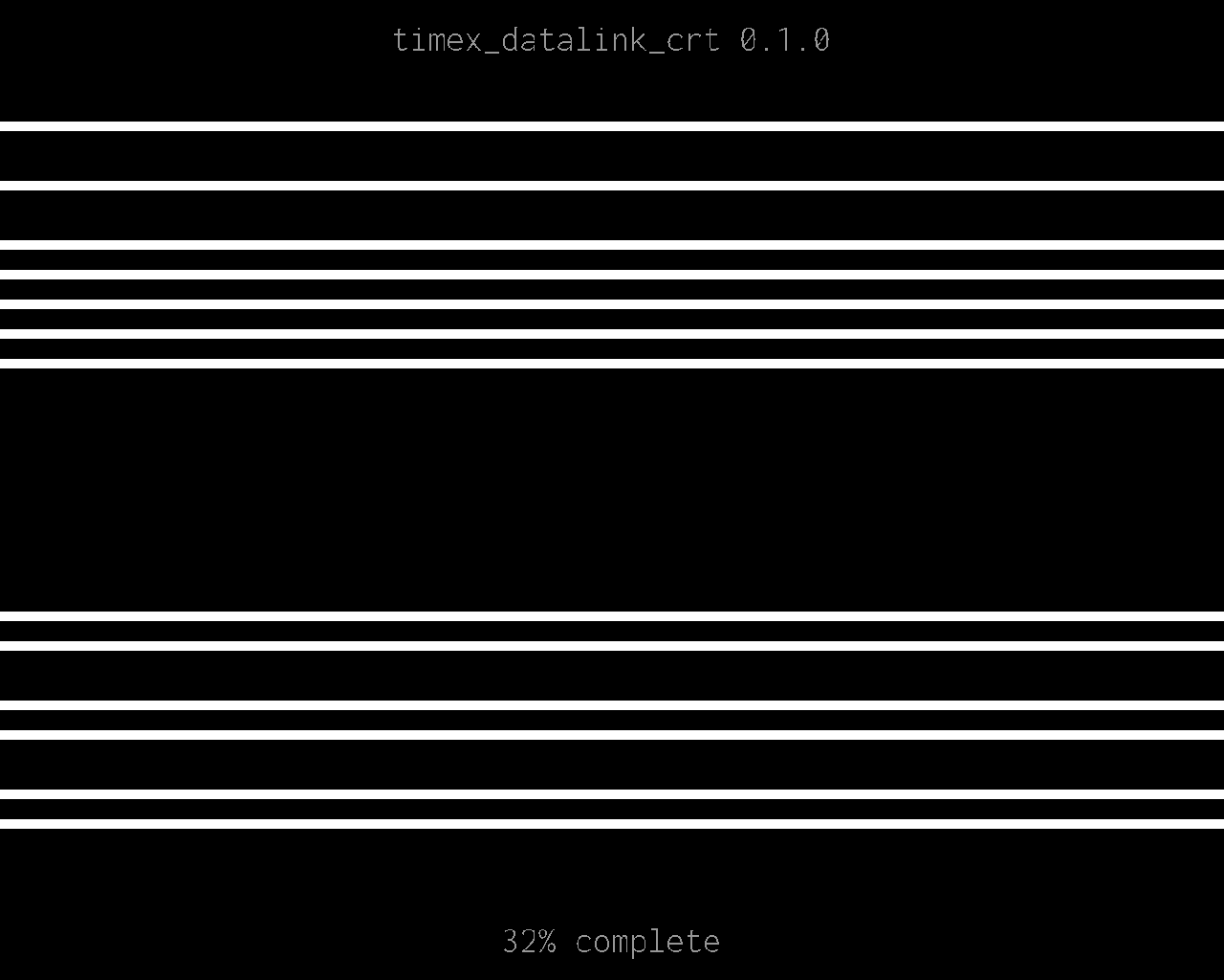
The original data transfer method involves drawing patterns of lines on a CRT monitor for the watch to receive with the optical sensor. CRTs use electron beams that draw scan lines one-by-one from top to bottom, then it returns to the top and repeats for the next frame. This means that the electron guns turn on when its drawing a white line, and and turn off when its drawing the black background. This produces flashing light as the graphics are drawn, which is ultimately received by the optical sensor and decoded by the Timex Datalink device.
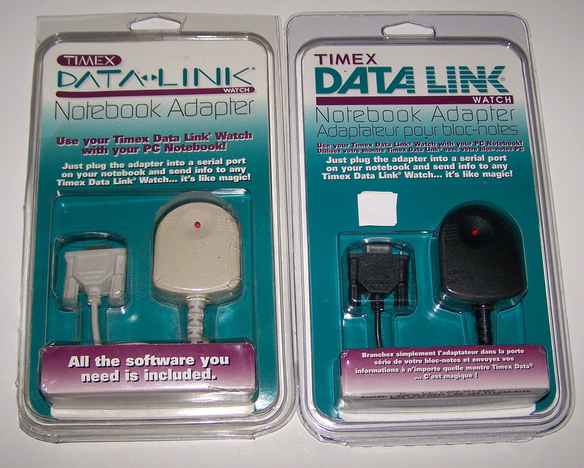
For laptop users, Timex also offered the Datalink Notebook Adapter. Instead of using a CRT monitor, the Notebook Adapter simply flashed a single LED light. This adapter is fully supported by the Timex Datalink software, and sends the same data as a CRT.
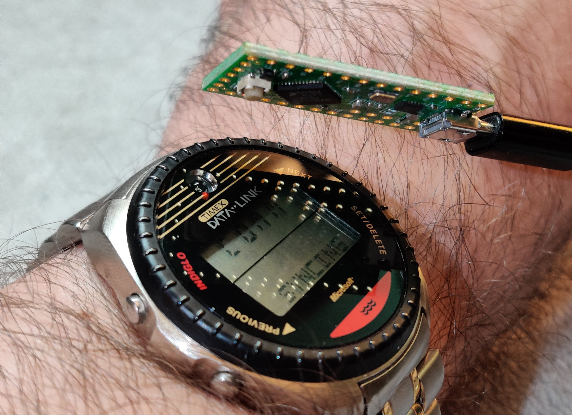
However, Notebook Adapters are rare and expensive now, so I reverse-engineered one! Here’s my timex_datalink_client Ruby library communicating with my DIY Datalink Notebook Adapter to emit data to a Timex Datalink watch!
And if you want to try the reverse-engineered CRT graphics, I got you covered! I reverse-engineered that, too!
As a fun tidbit, these watches are flight certified by NASA and is one of four watches qualified by NASA for space travel! Here’s a shot of James H. Newman wearing a Datalink watch on the Space Shuttle for STS-88!

Here is my Ruby library with all options for all watches reverse-engineered into a tidy model-based syntax!
Here is a Notebook Adapter emulator that is fully compatible with all Timex software on old and new machines, and also works with my library too!
And if you have an anchor that happens to contain an electron beam and wanna try it, here’s my library for drawing graphics to a CRT to transfer data!
This has all been done over months of careful effort with lots of VMs, Pentium machines, Windows 98SE, logic analyzers, and solving data puzzles little by little. On July 4th, 2023, I’m proud to announce that I have reverse-engineered every Datalink device with 100% feature compatibility! This is definitely a passion project by all means, and I thought I’d pop in and share this passion with y’all!
Enjoy!


OMG! I still have my DataLink watch somewhere. I remember thinking it was amazing and showing off all the phone numbers I’d programmed into it.
Will your code work with any flashing LED? Or does it need special hardware?
Seems to work with any Arduino based board, either ones with a internal led or external.
This library works with a Notebook Adapter, which could be one of the original DB9 RS232C serial devices or a DIY emulator like https://github.com/synthead/timex-datalink-arduino! Here is a Teensy LC running timex-datalink-arduino, syncing a Datalink 150 using its onboard LED!
The small onboard LED allows a Timex Datalink 150 watch to sync from a few inches away. With an external LED, it is possible to sync your watch from several feet away.
An LED can be added tidily to the Teensy LC by soldering an LED cathode (short leg) to the ground pin near the PROG pin, then connecting the anode (long leg) to pin 13 with a resistor, as pictured below.
I discovered that the best performance is obtained by using white LEDs, but every color I tested worked without problems. The LED pictured above is a white 20mA/3-3.2V 14000mcd LED paired with a stiff ¼W 22Ω resistor.